
Page 214 - Elpress英文样本电气连接压接系统
P. 214
System structure and function - deep earthing
Earthing Resistivity
An earth connection is a conductor The electrical properties of the soil are
placed in the soil, with the aim of divert- quality declared by means of its resis-
ing electrical current from an installation tivity, which is measured in Ωm (former
connected to the earth connection and unit Ωcm, 1 Ωm =100 Ωcm). Soil with
into the surrounding soil. good electrical conductivity thus has low
A customer who buys power takes resistivity: 10 - 100 Ωm.
earthing for granted. This is despite the For each case of different soil type, soil
fact that the use of power without, or resistance must be measured and prefer-
with poor, earthing incurs great risks. ably during several seasons and in differ-
All power suppliers must have approved ent weather conditions. In measurement
earth connections at their installations. today almost exclusively voltage compen-
This means that voltage surges that can sated electronic resistance bridges are
occur for various reasons are led into the used (measurement method according to
ground so that they do not cause dam- Wenner) with 4 connection contacts, 2 of
age. Earthing thus functions as, among which are for current electrodes and 2 for
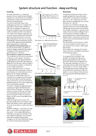
other things, personal protection, proper- Soil resistance in relation to temperature. voltage probes.
ty protection, signal transfer protection, The connectors are connected to 4 verti-
lightning protection and the like. cal metal tips that are driven down in a
An approved earthing should have: (1) row about 0.3-0.5 m deep a metre apart.
low electrical resistance, (2) ability to (See image)
conduct voltage stably (despite weather If the instrument reading is R, the resis-
changes) and (3) long service life, i.e. tivity of the soil is calculated according to
good resistance to corrosion. the following equation:
Soil conditions or external conditions? p = 2 x a x R Ωm
The importance of the soil as a conductor In unlayered soil, resistivity is inde-
of electric current is great. The techni- pendent of the electrode distance a.
cal specifications and requirements for By increasing distance a, the current
earthing demonstrate the advantages of penetrates deeper into the ground and
deep-earth connections, both as a techni- the measured resistivity can fall or in-
cal and economic solution, in relation to crease depending on the resistivity of the
surface-earth connections. ground layer at 1 metre’s depth. When
Current conduction occurs in the soil calculating approximate earthing resist-
through electrolytic processes, known as ance of the earth connection when the
ionic conduction. Solid particles such as depth is l, the resistivity of the soil must
gravel are not usually conductive. Soil resistance in relation to humidity. be measured with electrode distance a ≈
The electrical conductivity of the soil 0.75 x l.
therefore mainly depends on the propor-
tion of saline water bound by capillary
forces and osmotic pressure in the pores
between grains of sand and in hygroscop-
ic humus particles (e.g.clay).
The water in deeper lying ground layers
usually has a higher salinity than the
water in the surface layer. The higher the
moisture content of the soil, the better
the conductivity. Soil humidity normal-
ly varies between 5-40%. At variations
below 14-18%, conductivity deteriorates Measurement of ground resistance.
significantly.
Cold (frost) significantly impairs the
ground’s conductivity. It is of great impor-
tance that all this is taken into account
for earth connections or earth connection
systems. Resistivity in different soil conditions.
Weather conditions - cold, heat, rain and
wind - mainly affect the upper layer of
the soil (0 - 1.5 m), which therefore ex-
hibits the most powerful variations. The
most efficient earthing is thus reached
when the electrode is placed deep
enough so as not to be affected by chang-
es in soil humidity and temperature. Measuring earthing resistance of the
earth connection
11:8