
Page 258 - 世霸SuperToolVol.6
P. 258
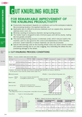
C UT KNURLING HOLDER


                 FOR REMARKABLE IMPROVEMENT OF

                 THE KNURLING PRODUCTIVITY

                      Productivity improvement depends on conditions such as the workpiece material,
                    the processing duration, the applied machine, etc.
                      Applicable also to difficult-to-process materials such as copper alloy, aluminum,
                    stainless steel, resin, etc.
                      Minimize swelling of workpiece diameter during knurling process.
    KNURLING HOLDERS & BITE HOLDERS
                      The holder head is designed to take minimum space and still be sturdy, making
                    the tool greatly versatile.
                      The load during knurling process is extremely small, which reduces load to the
                    machine, and it is also good for the control and maintenance of the machine
  Cut knurling
  holders,          precision. Small materials or hollow materials can also be processed.
  wheels
                      Special ball bearings used at the knurling wheel rotary axis allow smooth rotation
                    and prevent burning due to cut chip clogging, thus extending the wheel life and
                    preventing damage to the wheel.

  Roll knurling
  holders,      CUT KNURLING PROCESS CONDITIONS
  wheels

              ■ Table 1 Process condition table (approximate value)
                                        Material  Carbon   Mild steel  Stainless   Aluminum  Copper  Brass  Nylon resin
              External dia.                     steel              steel                             (* caution)
  Bite holders           Peripheral speed V(m/min)  40   50       30       80       50       60        50
                 φ5〜  φ12
                         Feed per revolution S’(mm/rev)    0.08    0.10    0.06    0.16    0.10    0.10    0.08
                         Peripheral speed V(m/min)  40   50       30       80       50       60        50
               φ12〜  φ50
                         Feed per revolution S’(mm/rev)    0.10    0.12    0.08    0.20    0.12    0.12    0.10
                         Peripheral speed V(m/min)  35   45       25       75       45       55        45
               φ50〜φ250
                         Feed per revolution S’(mm/rev)    0.10    0.12    0.08    0.20    0.12    0.12    0.10
              *  Caution : The values in the table are in reference with MC Nylon (MC901) and Duracon (MC90-44).
               For the values of other materials, please contact Super Tool.
              ■ Revolution speed                               ■ Table 2 Cross cut head swing angle chart

                     1000・V   D=processed material diameter(mm)
              N(rpm)=
                      π・D     V=peripheral speed(m/min)  drawing on the right 1
                                                          head swing angle scale
                                                                       2
              ■ Feed speed
                                                                       3
                              S'=feed per revolution S'(mm)
              Smm/min=N·S'                                             4
                              N=number of revolution per minute(rpm)
                                                                       5
              ■  Cutting amount                                        6
               The cutting amount of the cut knurling holder is about 80% of the knurling pitch.
                                                                       7
                                                                        3  8  27  64  125  250
              Tmm=P·0.8    P=pitch of the knurling wheel
                                                                processed material external diameter(mm)
                                Y
                                                    ■ Table 3 Stepped part process range (unit : mm)
                                                       KH1CN20N    KH1CA08,KH1CA10  KH2CN20N    KH2CA0.8,KH2CA10
                                           X           KH1CN25N    KH1CA12,(R)      KH2CN25N    KH2CA12,(R)
                                                     X (Step gap)  Y  X (Step gap)  Y  X (Step gap)  Y  X (Step gap)  Y
                                                       1〜4   1.5〜5  under 0.5  0.6  1〜4   1.5〜5  under 0.5  0.6
                                                      over 4  8.5   0.5〜2  0.6〜3.5  4〜7   5〜8.5   0.5〜2  0.6〜3.5
                                                                     2〜4   3.5〜5.5  7〜48   8.5    2〜4   3.5〜5.5
                                                                    over 4   5.5  over 48  25     over 4  5.5
                                                    *The values above are reference values. Refer to them as rough indications.


       256